An interrupt is a signal to the processor indicating an event has occurred that needs immediate attention. When an interrupt occurs, the address in the processors program counter register (PC) and the content of the other processor registers are saved in a storage area called the stack. The processor then jumps to the address of the appropriate interrupt service routine (ISR) in the Interrupt Vector Table and begins executing the interrupt service routine, or interrupt handler.
After the interrupt service routine completes, the processor pulls the pre-interrupt program counter contents and other the processor registers contents off the stack, restores them to the proper registers, The processor then returns to executing the program that was running before the interrupt occurred.
Hardware Interrupt
A hardware interrupt is a signal sent from a hardware device to a connection called the interrupt request line. The signal alerts the processor that the device needs attention. For example, when a keyboard key is pressed it sends a hardware interrupt signal that causes the processor to perform the interrupt service as described above. The interrupt service routine for a keyboard key press would cause the processor to read the keys code and sent it to the application or operating system. Other hardware devices that use hardware interrupts are the mouse, a disk controller, communications port, or other external peripheral.
8259A Programmable Interrupt Controller (PIC)

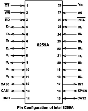
The 8259A Programmable Interrupt Controller (PIC) was designed to work with early Intel microprocessors. IR0-IR7 (Interrupt Request inputs): These are asynchronous interrupt request input pins. The chip can be programmed to accept level triggered or edge triggered interrupt requests, however, all interrupts must be triggered the same.
Nine 8259As can be cascaded in a master-slave configuration mode to handle 64 interrupt inputs. The CAS2-0 lines form a local 8259A bus to control multiple 8259As in master-slave configuration.
D7-D0 (Data Bus): Bidirectional data bus. Control, status and interrupt vector information is transferred via this data bus.
INT (Interrupt output): This pin goes high whenever a valid interrupt request is asserted. It is used to interrupt the CPU.
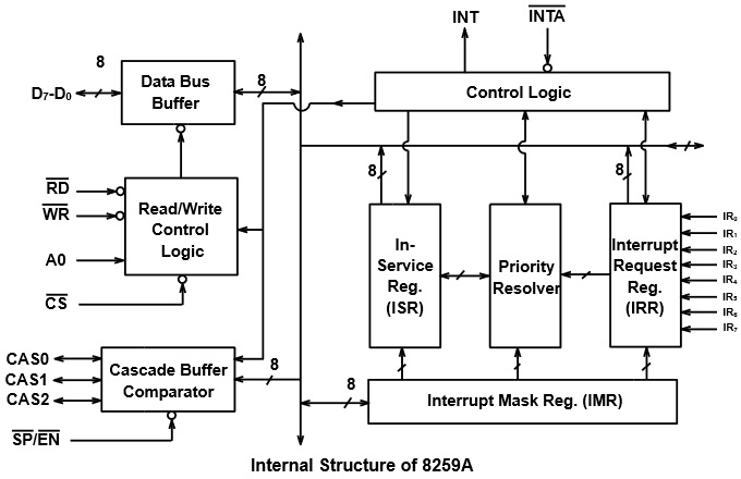
8259A PIC Internal Structure

The Interrupt Request Register (IRR) stores all the interrupt inputs that are requesting service. It is an 8-bit register – one bit for each interrupt request. It keeps track of which interrupt inputs are asking for service. If an interrupt input is unmasked, and has an interrupt signal on it, then the corresponding bit in the IRR will be set. The content of this register can be read to know the status of pending interrupts.
Each of the interrupt requests can be masked. The Interrupt Mask Register (IMR) is used to disable (Mask) or enable (Unmask) individual interrupt request inputs. This is also an 8-bit register. Each bit in this register corresponds to the interrupt input with the same number. The IMR operates on the IRR. Masking of higher priority input will not affect the interrupt request lines of lower priority. To unmask any interrupt the corresponding bit is set to 0.
The In Service Register (ISR) keeps track of which interrupt inputs are currently being serviced. For each input that is currently being serviced the corresponding bit of in-service register (ISR) will be set. In 8259A, during the service of an interrupt request, if another higher priority interrupt becomes active, it will be acknowledged and the control will be transferred from lower priority interrupt service subroutine (ISS) to higher priority ISS. Thus, more than one bit of ISR will be set indicating the number of interrupts being serviced.
Each of these three registers, IRR, IMR, and ISR can be read as a status register.
Priority Resolver: This logic block determines the priorities of the interrupts set in the IRR. It takes the information from IRR, IMR and ISR to determine whether the new interrupt request is having highest priority or not. If the new interrupt request is having the highest priority, it is selected and processed. The corresponding bit of ISR will be set during interrupt acknowledge machine cycle.
Interrupt Priority
The Interrupt Vector Table has a field that allows you to assign a priority level from 0 to 255 to an interrupt priority level 0 is the highest priority level, and priority level 255 is the lowest. If two interrupts occur simultaneously, the interrupt with the higher priority is serviced first.
If a higher priority interrupt occurs while a lower interrupt routine is being executed, the lower priority interrupt will be interrupted, the processors state being pushed to the top of the stack as described above, and the higher priority interrupt service routine will be executed.
After the higher priority interrupt service routine completes, the lower priority interrupt's processors state will be pulled from the top of the stack and the lower priority interrupt service routine will be executed. When the lower priority interrupt service routine completes, the processor pulls the pre-interrupts processor state off the stack and returns to executing the program that was running before the interrupts occurred.
Interupt Mask
An interrupt (hardware interrupt) will be ignored if it's associated bit in the mask register is set. There are also interrupts that lack an associated bit-mask Non-maskable interrupt (NMI). NMIs are used for the highest priority tasks so that its interrupt can never be ignored.
Software Interrupt
A software interrupt does not use the hardware interrupt request line, but is instead initiated by a program instruction. The operand of the instruction identifies the interrupt routine to be executed. A software interrupt is handled the same as a hardware interrupt as far as the processors state being pushed to the top of the stack, the associated service routine is run, after the service routine completes, the processor pulls the pre-interrupt processor state off the stack and returns to executing the program that was running before the interrupt occurred.
Exception Interrupt
An exception interrupt is caused by some illegal activity, for example dividing by zero, that sets a flag in a processor internal register. The exception interrupt may be handled by a kernel routine or an operating system service.
Polling
Polling is an alternative to the interrupt method of responding to a program or hardware device that needs attention. To perform polling requires repeatedly checking the status of a program or hardware device. The circuit may contain a register where am associated status bit is set when attention is needed. When the status bit is checked and found to be set, the appropriate service routine may be executed.
After the service routine has completed, the status bit is cleared and the polling resumes. There is a certain time interval before each time a status bit is polled, so the polling method has higher latency than the interrupt method. Also, polling is inefficient when a program or hardware device is polled repeatedly, but rarely needs service.
More Computer Architecture Articles:
• Operating System Memory Paging Hardware Support
• Pentium P5 Processor
• Microcontroller's Parallel I/O System
• AMD's Phenom Processor
• Round-Robin CPU Scheduling Algorithm
• The Many Processes of Silicon Wafer Manufacturing
• Operating System Memory Paging - Page Table Structure
• Difference between Stack, Heap, and Queue
• Challenges of Programming Multicore Systems
• How Computer Chips are Made

