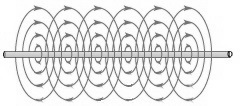
It was Michael Faraday, in 1831, who first noticed that direct current passing through a wire creates a magnetic field around the wire. He also noted that moving a magnet near a wire induced an electric current in the wire. Faraday explained electromagnetic induction using a concept he called lines of force. Today electromagnetic induction is the principle that is used in all electric motors and in electric transformers. Without electromagnetic induction we would be living in a primitive world indeed.
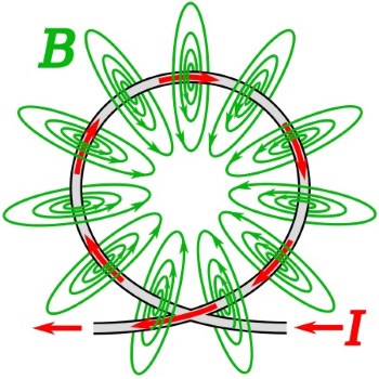
Magnetic field lines (B, green) of a wire loop carrying an electric current (I, red), illustrating how
the field lines all pass through the interior of the loop, creating a strong magnetic field there.
If the wire is formed into a circle, and an electric current is passed through the wire, the magnetic lines of force would go through the center of the circle. The magnetic flux would be densest in the middle of the circle. Conversely, if a magnet was pushed through the center of the circle, it would induce an electric current in the circle of wire.
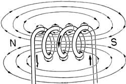
If the wire is formed into a coil, and a direct current is passed through the wire, the combined lines of force will create a magnetic field with with the polarity shown above. Note that the magnetic lines of force circle around the outside of the coil to complete a magnetic circuit.
When a certain high current is passed through the coil, the coil's magnetic field will become saturated. Saturation is the state reached when an increase in applied current does not increase the magnetic flux density of the coil. However the flux density and the strength of the magnetic field can be increased by placing an iron core in the coil.
• Reluctance is measure of a material's opposition to magnetic flux.
• Permeability is a measure a material's support for the formation of a magnetic field within itself.
An iron core has at least 1,000 more permeability than air. Iron ferrite material can be up to 10,000 times more permeable than air. Therefore an iron or ferrite core inceases the indictance of a coil. An undesireable side effect of high permeability is magnetic hysteresis. When a magnetic field is created in ferromagnetic material, even when the field is removed, the material will stay partially magnetized. It requires a magnetic field in the opposite direction to demagnetize it. This becomes a desirable effect when used in a computer hard disk to retain memory.
Another undesireable side effect of using ferromagnetic material is that it is a conducting material, and a changing magnetic field will induce currents within the material itself. These currents, called eddy currents don't do any useful work, and they produces a loss in the magnetic material and generate waste heat in the magnetic material.
• Reactance is the opposition to the change of current flow through an element. When direct current is first applied to an inductor, it takes a short period of time for the magnetic field to build. This is because the expanding magnetic field induces an EMF (electomotive force) in the coil. Since this force opposes the supplied current, it is referred to as CEMF (counter-electromotive force), also known as the back electromotive force.
This CEMF lasts only so long as the magnetic field is building. After the field reaches its full strength and stops increasing, current flows through the coil with only resistance limiting its value. Since the coil consists of a highly conductive material, it is wise to place some resistance in series with the coil to limit current flow.
• Note that the effect of CEMF, a delay in the build up of current, is opposite to the behavior of a capacitor. A capacitor initially has a high current that builds up a charge that opposes the flow of current, until it is fully charged, at which point it blocks current flow. An inductor initially has a low current, until the magnetic field stopsbuilding, at which point it allows high current flow.
If the flow of direct current though an inductor is abruptly stopped, for example by opening a switch, the magnetic field collapses rapidly, releasing its stored energy, and causing a strong pulse of EMF. This high pulse of current can be very damaging to electronic components. It is typically dealt with by connecting a diode in parallel with the coil, thereby shorting out the reverse current pulse. This diode is sometimes called a snubber diode.
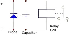
In a snubber circuit, a diode in combination
with a capacitor is commonly used.
Calculating Inductance
The magnetic inductance of a coil is measured with a unit called a Henry named after Joseph Henry, the American scientist and engineer who discovered several magnetic phenomenon. If the rate of change of current in a coil is 1 amp per second, and the induced EMF is 1 volt, the inductance of the coil is 1 Henry. However a Henry is quite a large unit and practical inductances are expressed in millihenrys (1 H = 1,000 mH), or microhenrys (1 mH = 1,000 uH), or nanohenrys (1 uH = 1,000 nH).

L = inductance in uH (microhenrys)
d = coil diameter in inches (from wire center to wire center)
n = number of turns
l = coil length in inches
Note that this formula calculates a coils inductance with air as the core. If a higher permeability core material is used then the more complex formual shown below must be used.
L = (N^2 * uA) l
L = inductance in henrys
N = number of turns
u = permiability
A = area of coil (pi*r^2) in meters
l = coil length in meters
Inductors in Series
L = L1 + L2 + L3 ...
In series, all the coils share the same current, and see the same rate of change in current, therefore the total inductance is the sum of all the individual indctances.
Inductors in Parallel
In parallel the current distributes itself acording to the inductances.
1/L = 1/L1 + 1/L2 + 1/L3 ...
LR Time Constant

Shown above is the equation for the current through a coil relative to the time after which the source voltage is applied. If you just need a rough estimate and you don’t feel like dealing with calculus integrals and differentials, you can use the L/R time constant method instead.
t = L/R
Were L is the value of the inductor in Henries and R is the value of the series resistancer in ohms.
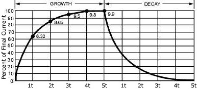
The time constant of an inductor is the rate at which it overcomes the CEMF generated by the coil and allows current to pass through it. It requires 1 time constant for the current in an inductor to increase to 63.2 percent of the maximum current. It requires another 1 time constant for the current to increase by 63.2 percent of the difference between the current flowing in the inductor and the maximum current. And so on, until after 5 time constants the current reachs its maximum steady state value.
More Computer Architecture Articles:
• The Microcontroller Interrupt System
• Intel's Core i7 Processors
• Computer Video Display
• Digital Logic Levels and Transfer Characteristics
• Intel's Sandy Bridge Micro-Architecture
• Intel's Core 2 Processors
• Multicore Programming
• Load Balancing Multiple CPUs in Symmetric Multiprocessing
• Capacitors in DC Circuits
• Stored Program Architecture

