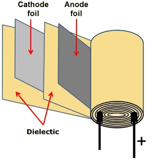
A capacitor is a component that can be used to store an electrical charge. Its basic design is two plates, each with a lead attached for connection to a circuit. The plates are separated by a thin insulator called a dielectic. Commonly, the plates are made from thin metal foil, and the dielectic is a thin film. The plates and dielectic film may be rolled up to form a cylindrical package.

When connected across a voltage source, electrons will flow onto the plate connected to the negative side of the power source. These will repel electrons from the other plate, causing a charge across the capacitor.
The amount of charge held on a capacitor's plate is measured in units called farads (F) after Michael Faraday. He is the English scientist who discovered electromagnetic induction, the principle behind the electric transformer, motor, and generator. A farad is the charge of 6.25 billion billion electrons.
A capacitor that can be charged to a potential difference between its plates of 1 volt in a time of 1 second during which it draws 1 amp has a capacitance of 1 farad. Because the farad is an Impractically large unit, capacitances are measured in smaller units.
1F = 1,000,000 uF (microfarads)
1uF = 1,000 nF (nanofarads)
1nF = 1,000 pF (picofarads)
Without a resistor in series, current would flow into the capacitor very quickly and the capacitor would act like a short circuit. Similarly, if the leads of a charged capacitor were connected to each other without a resistor in series, current would flow very quickly and the discharge would create a spark.
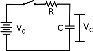
A capacitor used with a resistor in series requires a finite time to discharge. A capacitor can be used to create a timer. This time delay can be used to smooth a changing current flow in a circuit, or it can be used to absorb spikes and prevent false triggering of other components.
When a capacitor is placed in series with a resistor across a DC power source, it initially has no charge on its plates and no voltage across it. In the circuit shown above, when the switch is closed, electrons begin flowing through the resistor onto the capacitor's plates.
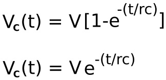
Shown above are equations for the voltage across a capacitor while charging (top) and discharging (bottom).
Vc = capacitor voltage
V = supply voltage
R = resitance
C = capacitance
t = time
e = 2.71828
The number e is the natural logarithm. The constant was discovered by the Swiss mathematician Jacob Bernoulli, but it is sometimes called Euler's constant after the Swiss mathematician Leonhard Euler who chose the symbol e to represent it. The number e is a magical number like pi which keeps reappearing in mathematics and nature.
With the equations above, you can calculate the voltage across the capacitor for any instant in time after which the power source is applied. However, if you need only a rough idea of this voltage, you can use the time constant method. The time constant is calculated by multiplying the value of the series resistor in ohms by the value of the capacitor in farads. The result is the time in seconds required for the capacitor to charge up to 63 percent of the supply voltage.
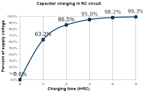
Image Source: Electrical Engineering Stack Exchange
http://electronics.stackexchange.com
After an additional time constant interval of time, the capacitor will charge up another 63 percent of the remaining voltage difference between it and the supply voltage. After each additional time constant, the capacitor voltage increases another 63 percent of the difference between it and the supply voltage, until after 5 time constants, the capacitor is charged up to (for all practical purposes) the supply voltage.
| Charging | |
| time constant | voltage % of max |
| 1 | 63.2 |
| 2 | 86.5 |
| 3 | 95.0 |
| 4 | 98.2 |
| 5 | 99.3 |
| Discharging | |
| time constant | voltage % of max |
| 1 | 36.6 |
| 2 | 13.5 |
| 3 | 5.0 |
| 4 | 1.8 |
| 5 | 0.7 |
![]()
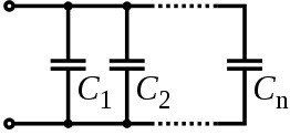
The equivalent capacitance of any number of capacitors connected in parallel is the total capacitances of all the capacitors.


The equivalent capacitance of any number of capacitors connected in series is the reciprocal of the sum of the reciprocals of all the capacitors.
More Computer Architecture Articles:
• The Motherboard Chipset
• Operating System Memory Paging
• Multi-Processor Scheduling
• Intel's Core i7 Processors
• Online Color Coded Resistor Calculator
• Getting started with Raspberry Pi
• Analog to Digital Convertion with a Microcontroller
• Binary Number Representation and Binary Math
• Multiuser Operating System Functions
• The AMD Athlon 64 X2 Processor

