If you view a computer as an input-processing-output machine, you can use a keyboard or removable storage device as the input, a program as the processing, but what can you use to retrieve the output? One way to acquire the output, be it text or graphics, is with a video display.
![]()
Before we go into the details of how the microprocessor gets involved with the video display, lets learn exactly how a video display works. We'll start by describing a monochrome display. If you were to examine the display with a magnifying glass, you would see that it is covered with dots. These dots are called pixels, short for "picture elements".
![]()
The picture above shows how, by turning on certain pixels, and turning off other pixels, the letter "E" can be created on the display. Early displays were a matrix 640 pixels wide and 480 pixels high.

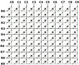
A matrix of pixels can be made using LEDs (Light Emitting Diodes). A schematic for a matrix of LEDs is shown above. If ground is applied to a specific row and a positive voltage is applied to a specific column, the LED at the intersection of that row and column would light up. Using this method multiple LEDs can be turned on Simultaneously, thus creating a desired letter or graphic shape.

How an OLED Works
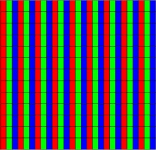
If you were to examine a modern OLED (Organic LED) display with a magnifying glass, you would see that it is covered with red, green, and blue rectangles. An organic LED is similar to a regular LED, except the material that emits light in response to an electric current is an electroluminescent organic compound rather than a semiconductor crystal.

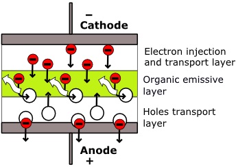
Electrons from the cathode pass through an electron transport layer from which they are injected into the emissive layer. Electrons are removed from the anode, creating holes. Electrons drop into holes that are entering the emissive layer, releasing some of their energy as light.
Computer displays generate various colors by using red, green, and blue (RGB) as the primary colors. Each pixel consists of a red, green, and blue OLED. By controlling the brightness of each OLED various colors can be created.
![]()
The color of an OLED can be controlled by the type of electroluminescent compound used, or all white light emitting OLEDs can be used with red, green, and blue filters placed in front of them.
How Colors are Coded
A Computer creates colors by defining the amount of red, green, and blue (RGB) in the color. The amount of a color is set by a number from 0 to 255 (00 to FF hexadecimal). For example, the code for the color cornflowerblue is #6495ed (the # sign indicating that this is a hexadecimal number). That means the amount of red is set to #64, the amount of green is set to #95, and the amount of blue is set to #ed.
The code #6495ed uses 24 bits, and so is called "True Color". However today, a 32-bit color scheme called RGBA is becoming the standard. The "A" stands for "alpha" and is a number from 0 to 255 (00 to FF hexadecimal) that sets the amount of opacity. If A is set for 0, the color the color is completely transparent (basically you have no color). If A is set for #FF, the color is completely opaque, not able to be seen through. Therefore, the complete RGBA code for cornflowerblue is #6495edff

Your basic computer video circuit is called VGA (Video Graphics Array). It converts the digital data in video memory to analog data required by the display.
How Screen Data is Stored
Each pixel on a computer screen has a corresponding location in memory where its RGBA code is stored. A 640 by 480 pixel display would require 307200 32-bit RAM (Random Access Memory) locations. That's about 1.2 megabytes (1.171875) of memory. Today 1280 by 1024 pixels is a very popular screen resolution, that requires 5 megabytes (5242880 bytes) of memory.
The location of this video memory varies depending upon the systems design. Some systems simply share main memory for use as video memory. Some systems use a video adapter plugged into an expansion slot on the motherboard. Some systems have a special graphics processor and video memory built-in to the motherboard. And, as is common today, some systems have the video circuitry integrated into the microprocessor chip.

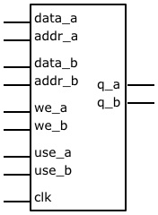
This pin diagram represents a generic dual-port video RAM. data_a and addr_a represent the data and address inputs for port A. data_b and addr_b represent the data and address inputs for port B. we_a is the control line for writing to port A. we_b is the control line for writing to port B. q_a and q_b are the port A and Port B data outputs. use_a and use_b select which port to output.
Because each pixel on a computer screen has a corresponding location in memory where its RGBA code is stored, this is called "bit-mapped" graphics. In order to produce graphic animation or video, the video memory must be updated at a very rapid rate. Using special high-speed dual-port memory helps with this, but still not fast enough. Therefore, several screen-sized areas of video memory (called frame buffers) are maintained. While one frame buffer is being transferred to the display screen, the next frame buffer is being written to with pixel data.
More Computer Architecture Articles:
• Dynamic Loading of Program Routines and Dynamically linked libraries (DLLs)
• Operating System Process Control Block
• Pentium P5 Processor
• The Computer's Chipset
• Change Raspberry Pi Default Configuration
• Multilevel Queue CPU Scheduling Algorithm
• Basic Electronics for Computer Architecture
• Arduino Microcontroller Development Platform
• Binary Floating-Point Numbers
• Microcontroller Architectures

